ما هو نظام الدورة في منصة الحفر؟
Oct 14, 2025
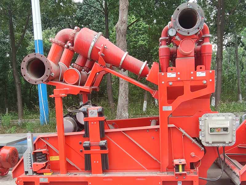
1. وحدة المعدات السطحيةخزان الطينالوظيفة: حاوية أساسية لتخزين وترسيب وإعداد سائل الحفر، تتكون عادة من 3-5 خزانات مستقلة (خزان شفط، خزان تنظيف، خزان احتياطي، خزان ترجيح) بسعة خزان واحد تتراوح بين 50-100 متر مكعب.مضخة الطينالوظيفة: في الغالب مضخة ترددية ثلاثية أحادية الفعل مع ضغط مخرج 30-100 ميجا باسكال وإزاحة 100-3000 لتر / دقيقة ؛ يستخرج سائل الحفر من خزان الشفط ويضغط عليه ويسلمه إلى مشعب السطح ، مما يوفر الطاقة للدوران في البئر.مشعب السطحالوظيفة: محور خط أنابيب يربط مضخة الطين، معدات التحكم في الدوران والمواد الصلبة، تتكون من أنبوب قائم، وخرطوم، صمام بوابة الطين، مقياس الضغط، وما إلى ذلك؛ يمكنه تبديل اتجاه تدفق سائل الحفر عبر صمامات البوابة، ويقوم مقياس الضغط بمراقبة ضغط الدورة في الوقت الفعلي لمنع حوادث الضغط الزائد.قطبالوظيفة: جهاز إغلاق دوار مثبت أسفل كتلة السفر، مع توصيل الطرف العلوي بالخرطوم وتوصيل الطرف السفلي بسلسلة الحفر؛ وهو يتيح الدوران المتزامن وتوصيل السوائل، مما يسمح لسلسلة الحفر بالدوران بسرعة عالية مع الحفاظ على نقل سائل الحفر بدون تسرب.معدات التحكم في المواد الصلبةالوظيفة: نظام تنقية وترشيح لسوائل الحفر، مقسم إلى أربعة مستويات حسب دقة التنقية:1.هزاز الصخر الزيتي (يزيل القطع الكبيرة، حجم الشاشة 0.2-1.5 ملم)؛2.ديساندر (يزيل جزيئات الرمل، حجم الفصل 40-74 ميكرومتر)؛3.مزيل الطمي (يزيل جزيئات الطين، حجم الفصل 15-40 ميكرومتر)؛4.أجهزة الطرد المركزي (يزيل الجسيمات الغروانية، حجم الفصل 2-15 ميكرومتر)؛يزيل أكثر من 95% من الجزيئات الصلبة من سائل الحفر لضمان خصائص مستقرة مثل اللزوجة والكثافة.2. عملية دوران سائل الحفرتتكون عملية تداول سائل الحفر من ثلاث مراحل أساسية، تشكل حلقة مغلقة كاملة، مع إجراءات محددة على النحو التالي:المرحلة 1: نزول سائل الحفر (السطح → الحفرة السفلية، توصيل الطاقة)1. تقوم مضخة الطين باستخراج سائل الحفر المُجهز من خزان الشفط، وتضغط عليه، وتوصله إلى أنبوب الوقوف لمشعب السطح؛2. يتدفق سائل الحفر عبر الأنبوب القائم إلى الخرطوم ثم إلى المحور الدوار؛3. يوجه المحور الدوار سائل الحفر إلى فتحة سلسلة الحفر من خلال هيكل الختم الدوار الخاص به، والذي يتدفق إلى الأسفل على طول القنوات المجوفة لأنبوب الحفر وياقة الحفر، ليصل في النهاية إلى بت الحفرة السفلية؛4. يتم قذف سائل الحفر بسرعة عالية من خلال فوهات الحفر، مما يشكل نفثة ضغط عالية للتأثير على تكوين الحفرة السفلية، ومساعدة الحفرة في كسر الصخور، وتسوية القطع في القاع.المرحلة الثانية: صعود سائل الحفر (الحفرة السفلية → السطح، تنفيذ الوظيفة)1. يلف سائل الحفر المقذوف عالي السرعة القطع المكسورة في الحفرة السفلية، مما يشكل خليطًا من القطع والطين؛2. بفضل الضغط المستمر لمضخة الطين، يتدفق الخليط إلى الأعلى على طول الحلقة، مع إكمال ثلاث مهام رئيسية:تبريد المثقاب: امتصاص الحرارة الناتجة عن دوران المثقاب (يمكن أن تصل درجة حرارة الفتحة السفلية إلى 150-200 درجة مئوية) ونقلها مرة أخرى إلى السطح من خلال الدورة الدموية؛تثبيت البئر: تشكل جزيئات الطين في سائل الحفر "كعكة طينية" بسمك 2-5 مم على جدار البئر، مما يؤدي إلى سد مسام التكوين ومنع انهيار البئر؛موازنة ضغط البئر: موازنة ضغط التكوين من خلال ضغط عمود سائل الحفر لمنع الانفجارات أو فقدان الدورة الدموية؛3. بعد أن يصل سائل الحفر المحمل بالقطع إلى السطح، فإنه يدخل أولاً إلى هزاز الصخر الزيتي للترشيح الأولي للقطع الكبيرة التي يزيد قطرها عن 0.2 مم.المرحلة 3: التنقية والتجديد (معالجة السطح، إعادة الاستخدام القابل لإعادة التدوير)1. يتدفق سائل الحفر الذي تم ترشيحه مسبقًا بواسطة هزاز الصخر الزيتي إلى جهاز إزالة الرمال، حيث يتم فصل جزيئات الرمل التي يبلغ قطرها 40-74 ميكرومتر بواسطة قوة الطرد المركزي؛2. يدخل سائل الحفر مع جزيئات الرمل المزال إلى وحدة إزالة الطمي لمزيد من فصل جزيئات الطين التي يبلغ قطرها 15-40 ميكرومتر؛3. بالنسبة للآبار العميقة/الآبار المعقدة ذات المتطلبات العالية، يحتاج سائل الحفر إلى الدخول إلى أجهزة الطرد المركزي لفصل الجسيمات الغروانية التي يبلغ قطرها 2-15 ميكرومتر؛4. يتدفق سائل الحفر المنقى إلى خزان التنظيف، حيث يقوم الفنيون بضبط خصائصه باستخدام أدوات الاختبار؛5. يدخل سائل الحفر المؤهل إلى خزان الشفط، في انتظار الدورة التالية لتحقيق إعادة الاستخدام بدون انبعاثات أو انبعاثات منخفضة.ثالثًا: الوظائف الأساسية الأربع لنظام الدورة الدموية1. حمل وإزالة القطع: منع حوادث التصاق الأنابيب2. تبريد وتزييت القطعة: إطالة عمر خدمة المعدات3. تثبيت البئر والتحكم في ضغط البئر: ضمان سلامة البئر4. نقل معلومات البئر: دعم الحفر الذكي
اقرأ أكثر


 Language :
 عربي
عربي English
 Русский
 إقتبس
إقتبس


 IPv6 دعم الشبكة